

DHT11 sensor with STM32
UPDATE
For those, whose code Runs only 1 time, Give at least 3 second delay in the while loop, before reading the temperature again.
If you are not able to get DHT11 or DHT22 values, Here is another method you can use. This one is unified for both the sensors. No setup is needed for timer and all. Just select the data pin as output and you are done. you need to select the DHT TYPE in DHT.c
https://controllerstech.com/wp-content/uploads/2020/06/DHT_11_22_DWT.zip
This CODE works with the TIMER Delay. If you want to know how to create delay in microsecond using timer, first go to https://controllerstech.com/create-1-microsecond-delay-stm32/
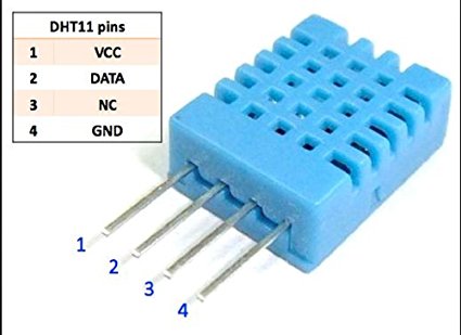
DHT11 digital temperature and humidity sensor is a composite Sensor contains a calibrated digital signal output of the temperature and humidity. Today in this tutorial we will be using DHT11 sensor with STM32.
INITIALIZATION
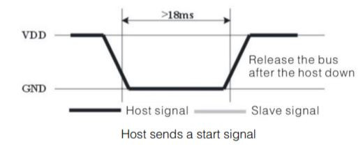
- As shown above, in order to initialize the sensor, we have to first pull the data line LOW for around 18 ms.
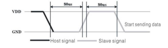
- After this DHT11 will pull the line LOW for 80 us ,and than HIGH for 80 us.
- Once this is done, the sensor will be initialized and start transmitting
NOTE:- You might need to connect pull-up resistor to the data line or else DHT11 will not be able to pull the line HIGH.
To initialize the sensor, the steps are as follows:-
- Set the pin (data) as output
- Pull the pin low for 18ms
- Release the pin by setting it as input
DHT11 will now send the response as you can see in the figure above.
Response
In order to indicate it’s presence, after receiving the start signal, DHT11 will send a response signal. To do so, it will pull the data line low for 80 us, and than high for another 80 us. To read this response, we will do the following
- Wait for 40 us
- Read the pin, it must be low at this point
- wait for 80 us
- Read the pin, this time it should be HIGH
If the above conditions are satisfied, that means the sensor is present, and we can proceed with reading the data.
DATA Transmission
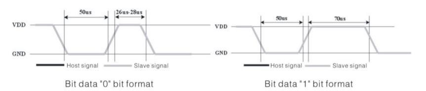
Now DHT11 will send 40 bits of data. Each bit’s transmission begins with low-voltage-level that last 50 us, the following high-voltage-level signal’s length decides whether the bit is “1” or “0”.
- If the length of high-voltage-level is around 26-28 us, the bit is “0”
- And if the length is around 70 us, than the bit is “1”
The 40 bits sent by DHT11 are as follows :
DATA = 8 bit integral RH data + 8 bit decimal RH data + 8 bit integral T data+8 bit decimal T data + 8 bit checksum
If the data transmission is right, check-sum should be the last 8 bit of “8 bit integral RH data+8 bit decimal RH data+8 bit integral T data+8 bit decimal T data”
Following are the steps to READ DATA from the sensor
- Wait for the pin to go high
- Wait for 40us. This is because the length of “0” bit is 26-28us, and if the pin is high after 40us, it indicates that the bit is “1”
- write the respective values to the variable
Connection
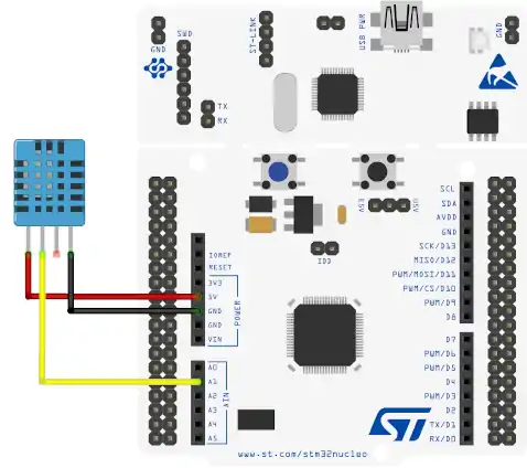
NOTE:- You might need to connect pull-up resistor to the data line or else DHT11 will not be able to pull the line HIGH.
Some Insight into the CODE
INITIALIZATION
- Set the pin (data) as output
- Pull the pin low and wait for 18ms
- set the pin as input for receiving the data
void DHT11_Start (void)
{
	Set_Pin_Output (DHT11_PORT, DHT11_PIN);  // set the pin as output
	HAL_GPIO_WritePin (DHT11_PORT, DHT11_PIN, 0);   // pull the pin low
	delay (18000);   // wait for 18ms
	Set_Pin_Input(DHT11_PORT, DHT11_PIN);    // set as input
}
RESPONSE
- wait for 40 us
- check if the pin is low, than wait for 80 us. This will totally be a delay of 120 us and the pin should be high now
- Check if the pin is high. If it is, than the response is OK
uint8_t Check_Response (void)
{
	uint8_t Response = 0;
	delay (40);
	if (!(HAL_GPIO_ReadPin (DHT11_PORT, DHT11_PIN)))
	{
		delay (80);
		if ((HAL_GPIO_ReadPin (DHT11_PORT, DHT11_PIN))) Response = 1;
		else Response = -1;
	}
	while ((HAL_GPIO_ReadPin (DHT11_PORT, DHT11_PIN)));   // wait for the pin to go low

	return Response;
}
READ DATA
- Wait for the pin to go high
- Wait for 40 us. This is because the length of “0” bit is 26-28 us and if the pin is high after 40 us, it indicates that the bit is “1”
- write the respective values to the variable
uint8_t DHT11_Read (void)
{
uint8_t i,j;
for (j=0;j<8;j++)
{
while (!(HAL_GPIO_ReadPin (DHT11_PORT, DHT11_PIN))); // wait for the pin to go high
delay (40); // wait for 40 us
if (!(HAL_GPIO_ReadPin (DHT11_PORT, DHT11_PIN))) // if the pin is low
{
i&= ~(1<<(7-j)); // write 0
}
else i|= (1<<(7-j)); // if the pin is high, write 1
while ((HAL_GPIO_ReadPin (DHT11_PORT, DHT11_PIN))); // wait for the pin to go low
}
return i;
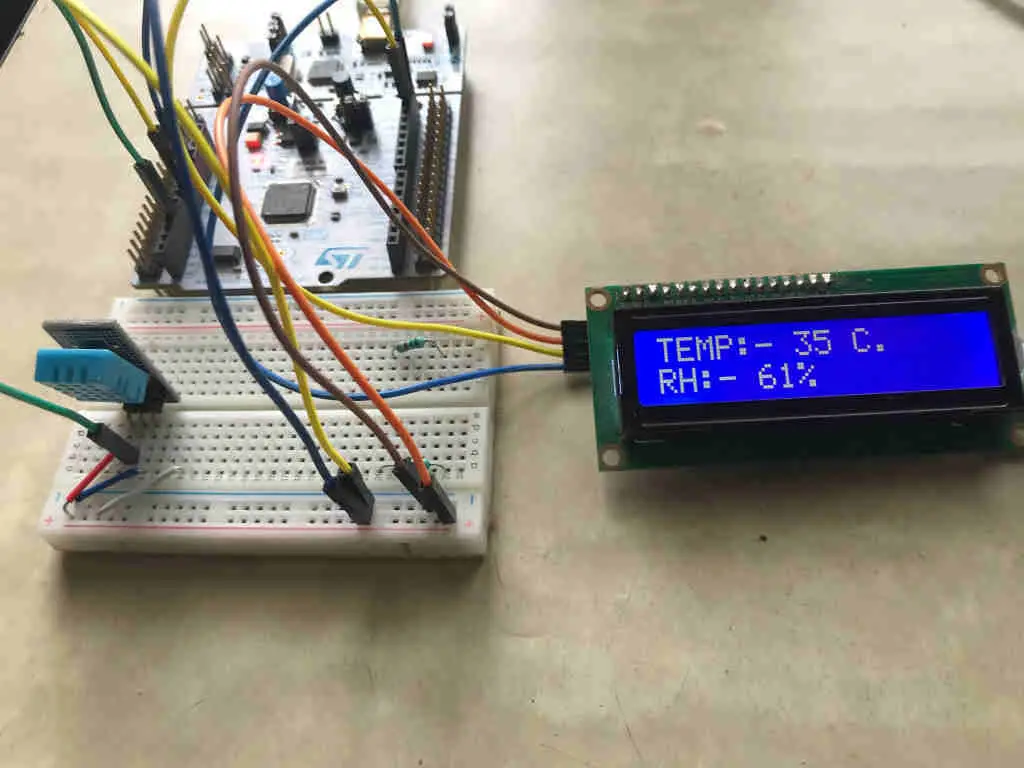
}Result


58 Comments. Leave new
That’s a very well written and clean library. Runs like a charm on my STM32F401RE Nucleo board and helps me a lot with debugging my own code – thank you!
Hello, thank you very much for your tutorial.
It will not work on STM32F103C8 unless you rewrite “delay” function. After that it will work ok.
buy cialis without a doctor’s prescription http://andere.strikingly.com/
Truly all kinds of great info!
i have problem when i put lcd_init() in main DTH not work ,but when i delete it DHT work probably
Hi
I have a problem with Delay microseconds, use STM32F103C8. It isn’t correct as I setup
Hi
my code gets stuck when go in the function DHT11_Check_Response in the “While (((HAL_GPIO_ReadPin (DHT11_PORT, DHT11_PIN)));”
can you look my code? :/
/* USER CODE BEGIN Header */
/**
******************************************************************************
* @file : main.c
* @brief : Main program body
******************************************************************************
* @attention
*
* <h2><center>© Copyright (c) 2020 STMicroelectronics.
* All rights reserved.</center></h2>
*
* This software component is licensed by ST under BSD 3-Clause license,
* the “License”; You may not use this file except in compliance with the
* License. You may obtain a copy of the License at:
* opensource.org/licenses/BSD-3-Clause
*
******************************************************************************
*/
/* USER CODE END Header */
/* Includes ——————————————————————*/
#include “main.h”
/* Private includes ———————————————————-*/
/* USER CODE BEGIN Includes */
//#include “i2c-lcd.h”
#include “stdio.h”
#include <stdlib.h>
#include “math.h”
#include “stdint.h”
#include <stdio.h>
#include <string.h>
/* USER CODE END Includes */
/* Private typedef ———————————————————–*/
/* USER CODE BEGIN PTD */
/* USER CODE END PTD */
/* Private define ————————————————————*/
/* USER CODE BEGIN PD */
/* USER CODE END PD */
/* Private macro ————————————————————-*/
/* USER CODE BEGIN PM */
/* USER CODE END PM */
/* Private variables ———————————————————*/
I2C_HandleTypeDef hi2c1;
TIM_HandleTypeDef htim6;
UART_HandleTypeDef huart2;
/* USER CODE BEGIN PV */
/* USER CODE END PV */
/* Private function prototypes ———————————————–*/
void SystemClock_Config(void);
static void MX_GPIO_Init(void);
static void MX_USART2_UART_Init(void);
static void MX_TIM6_Init(void);
static void MX_I2C1_Init(void);
/* USER CODE BEGIN PFP */
#ifdef __GNUC__
#define PUTCHAR_PROTOTYPE int __io_putchar(int ch)
#else
#define PUTCHAR_PROTORYPE int fputc (int ch, FILE *f)
#endif /* __GNUC__ */
PUTCHAR_PROTOTYPE
{
HAL_UART_Transmit(&huart2, (uint8_t *)&ch, 1, 0xFFFF);
return ch;
}
/* USER CODE END PFP */
/* Private user code ———————————————————*/
/* USER CODE BEGIN 0 */
void delay (uint16_t time)
{
/* change your code here for the delay in microseconds */
__HAL_TIM_SET_COUNTER(&htim6, 0);
while ((__HAL_TIM_GET_COUNTER(&htim6))<time);
}
void Display_Temp (float Temp)
{
char str[20] = {0};
//lcd_put_cur(0, 0);
uint8_t tempaux[]=”hola”;
HAL_UART_Transmit(&huart2, tempaux, sizeof(tempaux), 1000);
sprintf(str,”TEMP:- %.2f “, Temp);
//lcd_send_string(str);
//lcd_send_data(‘C’);
}
void Display_Rh (float Rh)
{
char str[20] = {0};
//lcd_put_cur(1, 0);
sprintf (str, “RH:- %.2f “, Rh);
//lcd_send_string(str);
//lcd_send_data(‘%’);
}
uint8_t Rh_byte1, Rh_byte2, Temp_byte1, Temp_byte2;
uint16_t SUM, RH, TEMP;
float Temperature = 0;
float Humidity = 0;
uint8_t Presence = 0;
void Set_Pin_Output (GPIO_TypeDef *GPIOx, uint16_t GPIO_Pin)
{
GPIO_InitTypeDef GPIO_InitStruct = {0};
GPIO_InitStruct.Pin = GPIO_Pin;
GPIO_InitStruct.Mode = GPIO_MODE_OUTPUT_PP;
GPIO_InitStruct.Speed = GPIO_SPEED_FREQ_LOW;
HAL_GPIO_Init(GPIOx, &GPIO_InitStruct);
}
void Set_Pin_Input (GPIO_TypeDef *GPIOx, uint16_t GPIO_Pin)
{
GPIO_InitTypeDef GPIO_InitStruct = {0};
GPIO_InitStruct.Pin = GPIO_Pin;
GPIO_InitStruct.Mode = GPIO_MODE_INPUT;
GPIO_InitStruct.Pull = GPIO_NOPULL;
HAL_GPIO_Init(GPIOx, &GPIO_InitStruct);
}
/*********************************** DHT11 FUNCTIONS ********************************************/
#define DHT11_PORT GPIOA
#define DHT11_PIN GPIO_PIN_1
void DHT11_Start (void)
{
Set_Pin_Output(DHT11_PORT, DHT11_PIN);
/* Nivel de comienzo de comunicación */
delay(1000);
HAL_GPIO_WritePin(DHT11_PORT, DHT11_PIN, 0);
delay (18000);
HAL_GPIO_WritePin(DHT11_PORT, DHT11_PIN, 1);
delay(20);
Set_Pin_Input(DHT11_PORT, DHT11_PIN);
}
uint8_t DHT11_Check_Response (void)
{
uint8_t Response = 0;
delay (40);
if (!(HAL_GPIO_ReadPin (DHT11_PORT, DHT11_PIN)))
{
delay (80);
if ((HAL_GPIO_ReadPin (DHT11_PORT, DHT11_PIN))) Response = 1;
else Response = -1; // 255
}
while ((HAL_GPIO_ReadPin (DHT11_PORT, DHT11_PIN))); // wait for the pin to go low
return Response;
}
uint8_t DHT11_Read (void)
{
uint8_t i,j;
for (j=0;j<8;j++)
{
while (!(HAL_GPIO_ReadPin (DHT11_PORT, DHT11_PIN))); // wait for the pin to go high
delay (40); // wait for 40 us
if (!(HAL_GPIO_ReadPin (DHT11_PORT, DHT11_PIN))) // if the pin is low
{
i&= ~(1<<(7-j)); // write 0
}
else i|= (1<<(7-j)); // if the pin is high, write 1
while ((HAL_GPIO_ReadPin (DHT11_PORT, DHT11_PIN))); // wait for the pin to go low
}
return i;
}
/* USER CODE END 0 */
/**
* @brief The application entry point.
* @retval int
*/
int main(void)
{
/* USER CODE BEGIN 1 */
/* USER CODE END 1 */
/* MCU Configuration——————————————————–*/
/* Reset of all peripherals, Initializes the Flash interface and the Systick. */
HAL_Init();
/* USER CODE BEGIN Init */
/* USER CODE END Init */
/* Configure the system clock */
SystemClock_Config();
/* USER CODE BEGIN SysInit */
/* USER CODE END SysInit */
/* Initialize all configured peripherals */
MX_GPIO_Init();
MX_USART2_UART_Init();
MX_TIM6_Init();
MX_I2C1_Init();
/* USER CODE BEGIN 2 */
HAL_TIM_Base_Start(&htim6);
// lcd_init();
// lcd_send_string(“INITIALISING>>>>”);
// HAL_Delay(2000);
// lcd_clear ();
/* USER CODE END 2 */
/* Infinite loop */
/* USER CODE BEGIN WHILE */
while (1)
{
/* USER CODE END WHILE */
/* USER CODE BEGIN 3 */
// Display_Temp(Temperature);
// Display_Rh(Humidity);
/********************** DHT11 *********************/
Display_Temp(Temperature);
Display_Rh(RH);
DHT11_Start();
Presence = DHT11_Check_Response();
Rh_byte1 = DHT11_Read ();
Rh_byte2 = DHT11_Read ();
Temp_byte1 = DHT11_Read ();
Temp_byte2 = DHT11_Read ();
SUM = DHT11_Read();
TEMP = Temp_byte1;
RH = Rh_byte1;
Temperature = (float) TEMP;
Humidity = (float) RH;
// Display_Temp(Temperature);
printf(“, %f\n\r*”,Temperature);
printf(“, %f\n\r*”,Humidity);
HAL_Delay(3000);
}
/* USER CODE END 3 */
}
/**
* @brief System Clock Configuration
* @retval None
*/
void SystemClock_Config(void)
{
RCC_OscInitTypeDef RCC_OscInitStruct = {0};
RCC_ClkInitTypeDef RCC_ClkInitStruct = {0};
RCC_PeriphCLKInitTypeDef PeriphClkInit = {0};
/** Initializes the RCC Oscillators according to the specified parameters
* in the RCC_OscInitTypeDef structure.
*/
RCC_OscInitStruct.OscillatorType = RCC_OSCILLATORTYPE_HSI|RCC_OSCILLATORTYPE_HSE;
RCC_OscInitStruct.HSEState = RCC_HSE_ON;
RCC_OscInitStruct.HSEPredivValue = RCC_HSE_PREDIV_DIV1;
RCC_OscInitStruct.HSIState = RCC_HSI_ON;
RCC_OscInitStruct.HSICalibrationValue = RCC_HSICALIBRATION_DEFAULT;
RCC_OscInitStruct.PLL.PLLState = RCC_PLL_ON;
RCC_OscInitStruct.PLL.PLLSource = RCC_PLLSOURCE_HSE;
RCC_OscInitStruct.PLL.PLLMUL = RCC_PLL_MUL9;
if (HAL_RCC_OscConfig(&RCC_OscInitStruct) != HAL_OK)
{
Error_Handler();
}
/** Initializes the CPU, AHB and APB buses clocks
*/
RCC_ClkInitStruct.ClockType = RCC_CLOCKTYPE_HCLK|RCC_CLOCKTYPE_SYSCLK
|RCC_CLOCKTYPE_PCLK1|RCC_CLOCKTYPE_PCLK2;
RCC_ClkInitStruct.SYSCLKSource = RCC_SYSCLKSOURCE_PLLCLK;
RCC_ClkInitStruct.AHBCLKDivider = RCC_SYSCLK_DIV1;
RCC_ClkInitStruct.APB1CLKDivider = RCC_HCLK_DIV2;
RCC_ClkInitStruct.APB2CLKDivider = RCC_HCLK_DIV1;
if (HAL_RCC_ClockConfig(&RCC_ClkInitStruct, FLASH_LATENCY_2) != HAL_OK)
{
Error_Handler();
}
PeriphClkInit.PeriphClockSelection = RCC_PERIPHCLK_I2C1;
PeriphClkInit.I2c1ClockSelection = RCC_I2C1CLKSOURCE_HSI;
if (HAL_RCCEx_PeriphCLKConfig(&PeriphClkInit) != HAL_OK)
{
Error_Handler();
}
}
/**
* @brief I2C1 Initialization Function
* @param None
* @retval None
*/
static void MX_I2C1_Init(void)
{
/* USER CODE BEGIN I2C1_Init 0 */
/* USER CODE END I2C1_Init 0 */
/* USER CODE BEGIN I2C1_Init 1 */
/* USER CODE END I2C1_Init 1 */
hi2c1.Instance = I2C1;
hi2c1.Init.Timing = 0x2000090E;
hi2c1.Init.OwnAddress1 = 0;
hi2c1.Init.AddressingMode = I2C_ADDRESSINGMODE_7BIT;
hi2c1.Init.DualAddressMode = I2C_DUALADDRESS_DISABLE;
hi2c1.Init.OwnAddress2 = 0;
hi2c1.Init.OwnAddress2Masks = I2C_OA2_NOMASK;
hi2c1.Init.GeneralCallMode = I2C_GENERALCALL_DISABLE;
hi2c1.Init.NoStretchMode = I2C_NOSTRETCH_DISABLE;
if (HAL_I2C_Init(&hi2c1) != HAL_OK)
{
Error_Handler();
}
/** Configure Analogue filter
*/
if (HAL_I2CEx_ConfigAnalogFilter(&hi2c1, I2C_ANALOGFILTER_ENABLE) != HAL_OK)
{
Error_Handler();
}
/** Configure Digital filter
*/
if (HAL_I2CEx_ConfigDigitalFilter(&hi2c1, 0) != HAL_OK)
{
Error_Handler();
}
/* USER CODE BEGIN I2C1_Init 2 */
/* USER CODE END I2C1_Init 2 */
}
/**
* @brief TIM6 Initialization Function
* @param None
* @retval None
*/
static void MX_TIM6_Init(void)
{
/* USER CODE BEGIN TIM6_Init 0 */
/* USER CODE END TIM6_Init 0 */
TIM_MasterConfigTypeDef sMasterConfig = {0};
/* USER CODE BEGIN TIM6_Init 1 */
/* USER CODE END TIM6_Init 1 */
htim6.Instance = TIM6;
htim6.Init.Prescaler = 50-1;
htim6.Init.CounterMode = TIM_COUNTERMODE_UP;
htim6.Init.Period = 0xffff;
htim6.Init.AutoReloadPreload = TIM_AUTORELOAD_PRELOAD_DISABLE;
if (HAL_TIM_Base_Init(&htim6) != HAL_OK)
{
Error_Handler();
}
sMasterConfig.MasterOutputTrigger = TIM_TRGO_RESET;
sMasterConfig.MasterSlaveMode = TIM_MASTERSLAVEMODE_DISABLE;
if (HAL_TIMEx_MasterConfigSynchronization(&htim6, &sMasterConfig) != HAL_OK)
{
Error_Handler();
}
/* USER CODE BEGIN TIM6_Init 2 */
/* USER CODE END TIM6_Init 2 */
}
/**
* @brief USART2 Initialization Function
* @param None
* @retval None
*/
static void MX_USART2_UART_Init(void)
{
/* USER CODE BEGIN USART2_Init 0 */
/* USER CODE END USART2_Init 0 */
/* USER CODE BEGIN USART2_Init 1 */
/* USER CODE END USART2_Init 1 */
huart2.Instance = USART2;
huart2.Init.BaudRate = 38400;
huart2.Init.WordLength = UART_WORDLENGTH_8B;
huart2.Init.StopBits = UART_STOPBITS_1;
huart2.Init.Parity = UART_PARITY_NONE;
huart2.Init.Mode = UART_MODE_TX_RX;
huart2.Init.HwFlowCtl = UART_HWCONTROL_NONE;
huart2.Init.OverSampling = UART_OVERSAMPLING_16;
huart2.Init.OneBitSampling = UART_ONE_BIT_SAMPLE_DISABLE;
huart2.AdvancedInit.AdvFeatureInit = UART_ADVFEATURE_NO_INIT;
if (HAL_UART_Init(&huart2) != HAL_OK)
{
Error_Handler();
}
/* USER CODE BEGIN USART2_Init 2 */
/* USER CODE END USART2_Init 2 */
}
/**
* @brief GPIO Initialization Function
* @param None
* @retval None
*/
static void MX_GPIO_Init(void)
{
GPIO_InitTypeDef GPIO_InitStruct = {0};
/* GPIO Ports Clock Enable */
__HAL_RCC_GPIOF_CLK_ENABLE();
__HAL_RCC_GPIOA_CLK_ENABLE();
__HAL_RCC_GPIOB_CLK_ENABLE();
/*Configure GPIO pin Output Level */
HAL_GPIO_WritePin(GPIOA, GPIO_PIN_1, GPIO_PIN_RESET);
/*Configure GPIO pin : PA1 */
GPIO_InitStruct.Pin = GPIO_PIN_1;
GPIO_InitStruct.Mode = GPIO_MODE_OUTPUT_PP;
GPIO_InitStruct.Pull = GPIO_NOPULL;
GPIO_InitStruct.Speed = GPIO_SPEED_FREQ_LOW;
HAL_GPIO_Init(GPIOA, &GPIO_InitStruct);
}
/* USER CODE BEGIN 4 */
/* USER CODE END 4 */
/**
* @brief This function is executed in case of error occurrence.
* @retval None
*/
void Error_Handler(void)
{
/* USER CODE BEGIN Error_Handler_Debug */
/* User can add his own implementation to report the HAL error return state */
/* USER CODE END Error_Handler_Debug */
}
#ifdef USE_FULL_ASSERT
/**
* @brief Reports the name of the source file and the source line number
* where the assert_param error has occurred.
* @param file: pointer to the source file name
* @param line: assert_param error line source number
* @retval None
*/
void assert_failed(uint8_t *file, uint32_t line)
{
/* USER CODE BEGIN 6 */
/* User can add his own implementation to report the file name and line number,
tex: printf(“Wrong parameters value: file %s on line %d\r\n”, file, line) */
/* USER CODE END 6 */
}
#endif /* USE_FULL_ASSERT */
/************************ (C) COPYRIGHT STMicroelectronics *****END OF FILE****/
Hello,
I might have gotten a little closer to figuring out why the hard-coded DHT11 code may not be working for myself and some other students based on some observations.
I have hard-coded the following steps as required by the DHT11 from your guide:
PA6 is set as datapin (this is different)
1. Set pin PA6 as output pin, pull-up resistor enabled, and set pin ‘LOW’ for 18 milliseconds delay
2. Set pin PA6 as input pin, delay for 40 microseconds, check if pin PA6 is low
3. If PA6 is low, delay 80 microseconds, set response variable “Response = 1”
4. Wait for pin PA6 to go low in while loop
5. Collect 40 bits of data in for loop nested within for loop, if pin is high for 28 microseconds or less, bit is ‘0’, if pin is high for >28 microseconds, bit is ‘1’
6. Obtain temp and humidity from bit shift operations
The code shown below runs well and even shows 40 bits being transmitted by the DHT11 as shown by a digital usb analyzer:
//:0
The code for this is presented below. If I try to include anything from the while loop on to the end of the code to collect data, I get a complete flat-line as shown below. It won’t even run the initial code that I’ve proven to work.
//:0
In both cases where I leave steps 4 – 6 out and when I include them, I make sure to put 3 seconds delay before reading the sensor again so as to rule this out. Any reason why the code refuses to work entirely with just the addition of that while loop?
#include “stm32f4xx.h” // Device header
#include “stdio.h”
#include “stdint.h”
#include <stdio.h>
#include <string.h>
void USART2_Init(void);
float TEMP, HUM;
void USART2_write(uint8_t* charString, uint16_t len);
void delayMicroseconds(uint32_t microseconds);
int main(void){
uint8_t DHT11_DATA[5] = {0, 0, 0, 0, 0};
uint8_t i, j = 0;
while(1){
RCC->AHB1ENR |= 0x1; //ENABLE GPIOA clock
GPIOA->MODER |= 0x1000; //Set pin PA6 as output mode
GPIOA->PUPDR |= 0x1000; //Pull-up resistor set for PA6
GPIOA->ODR &= ~0x40; //Set PA6 to LOW
delayMicroseconds(18000); //delay for 18 milliseconds
GPIOA->MODER &= ~0x1000; //Set pin PA6 as input mode*/
int Response = 0;
delayMicroseconds(40);
if(!(GPIOA->IDR & 0x40)) //
{
delayMicroseconds(80);
if(GPIOA->IDR & 0x40)
{
Response = 1;
}else{
Response = -1;
}
}
//while(GPIOA->IDR & 0x40); //Wait for pin to go low. DHT11 doesn’t run at all when this piece of code is active
/****This code left out until while loop shown to work*******************
for(i = 0; i < 5; i++)
{
for(j = 0; j < 8; j++)
{
while(!(GPIOA->IDR & 0x40)){}; //wait here while pin is low
delayMicroseconds(40);
if(!(GPIOA->IDR & 0x40))
{
DHT11_DATA[i] &= ~(1 << (7 – j)); //write 0 to bit
}
else DHT11_DATA[i] |= (1 << (7 – j)); //write 1 to bit
while(GPIOA->IDR & 0x40){}; //while pin is HIGH, hold here
}
}
TEMP = (float)DHT11_DATA[2];
HUM = (float)DHT11_DATA[0];
**************This code left out until while loop shown to work**********
delayMicroseconds(3000000);
}
}
static inline void delayMicroseconds(uint32_t microseconds)
{
RCC->APB1ENR |= 0x1; //ENABLE TIM2 clock
TIM2->PSC = 16 – 1;
TIM2->ARR = microseconds;
TIM2->CNT = 0;
TIM2->CR1 = 1;
while(!(TIM2->SR & 1)){};
TIM2->SR &= ~1;
TIM2->CR1 |= 0;
}
Hi
Thanks for your good job
My sensor worked with library but in this code it returns 255 or -1 as response
I know connection is ok
Can u help me?
check in the video description, i have posted one alternate code. That might help you
I ALSO HAVE PROBLEMS LIKE THIS. PLEASE HELP YOU HAVE RESOLVED
check the connection, pull up resistor etc
check timer frequency and make sure you are getting 1 us delay
try using that alternate code with DWT
Thank you for the tutorial. The code you created works very well. But there is a problem, the program can run properly in debug mode only. Without debugging i have to do a hard reset/power reset before the program can run. I use STM32F103C8 and Nucleo-L476RG.
thank you for helping out with this sensor …I have a project on gas sensor MQ2 ..Can u help me with the code for it with STM32 using CubeMx ….really need ur help?
I think i told u this already. It’s an ADC sensor, so just use the adc in that. If you have any problem, mail me admin@controllerstech.com
same the way, My code run only 1 time? :((
No Change humidity and temperature if I impact to it
what controller are u using ?
stm32f103c8t6
stm32f103c8t6
The code is alright. I tested it 2 days ago, and it was working fine. Maybe the connection, or the sensor… Try using the PULL UP Register, that might solve the issue
Hi, did you find the solution? I am facing the same problem
Hi! I’m using your code to get data from a DHT11 sensor on a STM32L053 by adapting it to work with 32Mhz clock and such… However the first acquisition goes ok and returns correct values on temp and humidity, but on the second loop it gets stuck on the check response function, it won’t leave the while loop waiting for the pin to go low. I’m using a 4.7K pull-up resistor on data pin… Any ideas? Thanks
try adding the delay of 500 ms or something between the acquisitions.
can u please check the code.I have put the timer also still it is not working .please help me …urgent
#include “main.h”
/* Private includes ———————————————————-*/
/* USER CODE BEGIN Includes */
/* USER CODE END Includes */
/* Private typedef ———————————————————–*/
/* USER CODE BEGIN PTD */
/* USER CODE END PTD */
/* Private define ————————————————————*/
/* USER CODE BEGIN PD */
/* USER CODE END PD */
/* Private macro ————————————————————-*/
/* USER CODE BEGIN PM */
/* USER CODE END PM */
/* Private variables ———————————————————*/
TIM_HandleTypeDef htim1;
UART_HandleTypeDef huart2;
/* USER CODE BEGIN PV */
/* USER CODE END PV */
/* Private function prototypes ———————————————–*/
void SystemClock_Config(void);
static void MX_GPIO_Init(void);
static void MX_TIM1_Init(void);
static void MX_USART2_UART_Init(void);
/* USER CODE BEGIN PFP */
/* USER CODE END PFP */
/* Private user code ———————————————————*/
/* USER CODE BEGIN 0 */
extern TIM_HandleTypeDef htim1;
void delay (uint32_t time)
{
/* change your code here for the delay in microseconds */
__HAL_TIM_SET_COUNTER(&htim1, 0);
while ((__HAL_TIM_GET_COUNTER(&htim1))<time);
}
#define DHT11_PORT GPIOA
#define DHT11_PIN GPIO_PIN_1
uint8_t Rh_byte1, Rh_byte2, Temp_byte1, Temp_byte2;
uint16_t sum, RH, TEMP;
uint8_t check = 0;
GPIO_InitTypeDef GPIO_InitStruct;
void set_gpio_output (void)
{
/*Configure GPIO pin output: PA2 */
GPIO_InitStruct.Pin = DHT11_PIN;
GPIO_InitStruct.Mode = GPIO_MODE_OUTPUT_PP;
GPIO_InitStruct.Speed = GPIO_SPEED_FREQ_LOW;
HAL_GPIO_Init(DHT11_PORT, &GPIO_InitStruct);
}
void set_gpio_input (void)
{
/*Configure GPIO pin input: PA2 */
GPIO_InitStruct.Pin = DHT11_PIN;
GPIO_InitStruct.Mode = GPIO_MODE_INPUT;
GPIO_InitStruct.Pull = GPIO_NOPULL;
HAL_GPIO_Init(DHT11_PORT, &GPIO_InitStruct);
}
void DHT11_start (void)
{
set_gpio_output (); // set the pin as output
HAL_GPIO_WritePin (DHT11_PORT, DHT11_PIN, 0); // pull the pin low
delay (18000); // wait for 18ms
set_gpio_input (); // set as input
}
void check_response (void)
{
delay (40);
if (!(HAL_GPIO_ReadPin (DHT11_PORT, DHT11_PIN)))
{
delay (80);
if ((HAL_GPIO_ReadPin (DHT11_PORT, DHT11_PIN))) check = 1;
}
while ((HAL_GPIO_ReadPin (DHT11_PORT, DHT11_PIN))); // wait for the pin to go low
}
uint8_t read_data (void)
{
uint8_t i=0,j;
for (j=0;j<8;j++)
{
while (!(HAL_GPIO_ReadPin (DHT11_PORT, DHT11_PIN))); // wait for the pin to go high
delay (40); // wait for 40 us
if ((HAL_GPIO_ReadPin (DHT11_PORT, DHT11_PIN)) == 0) // if the pin is low
{
i&= ~(1<<(7-j)); // write 0
}
else i|= (1<<(7-j)); // if the pin is high, write 1
while ((HAL_GPIO_ReadPin (DHT11_PORT, DHT11_PIN))); // wait for the pin to go low
}
return i;
}
/* USER CODE END 0 */
/**
* @brief The application entry point.
* @retval int
*/
int main(void)
{
/* USER CODE BEGIN 1 */
/* USER CODE END 1 */
/* MCU Configuration——————————————————–*/
/* Reset of all peripherals, Initializes the Flash interface and the Systick. */
HAL_Init();
/* USER CODE BEGIN Init */
/* USER CODE END Init */
/* Configure the system clock */
SystemClock_Config();
/* USER CODE BEGIN SysInit */
/* USER CODE END SysInit */
/* Initialize all configured peripherals */
MX_GPIO_Init();
MX_TIM1_Init();
MX_USART2_UART_Init();
/* USER CODE BEGIN 2 */
/* USER CODE END 2 */
/* Infinite loop */
/* USER CODE BEGIN WHILE */
while (1)
{
/* USER CODE END WHILE */
/* USER CODE BEGIN 3 */
DHT11_start ();
check_response ();
Rh_byte1 = read_data ();
Rh_byte2 = read_data ();
Temp_byte1 = read_data ();
Temp_byte2 = read_data ();
sum = read_data();
HAL_Delay(500);
}
/* USER CODE END 3 */
}
/**
* @brief System Clock Configuration
* @retval None
*/
void SystemClock_Config(void)
{
RCC_OscInitTypeDef RCC_OscInitStruct = {0};
RCC_ClkInitTypeDef RCC_ClkInitStruct = {0};
/** Configure the main internal regulator output voltage
*/
__HAL_RCC_PWR_CLK_ENABLE();
__HAL_PWR_VOLTAGESCALING_CONFIG(PWR_REGULATOR_VOLTAGE_SCALE2);
/** Initializes the CPU, AHB and APB busses clocks
*/
RCC_OscInitStruct.OscillatorType = RCC_OSCILLATORTYPE_HSE;
RCC_OscInitStruct.HSEState = RCC_HSE_ON;
RCC_OscInitStruct.PLL.PLLState = RCC_PLL_ON;
RCC_OscInitStruct.PLL.PLLSource = RCC_PLLSOURCE_HSE;
RCC_OscInitStruct.PLL.PLLM = 4;
RCC_OscInitStruct.PLL.PLLN = 84;
RCC_OscInitStruct.PLL.PLLP = RCC_PLLP_DIV2;
RCC_OscInitStruct.PLL.PLLQ = 7;
if (HAL_RCC_OscConfig(&RCC_OscInitStruct) != HAL_OK)
{
Error_Handler();
}
/** Initializes the CPU, AHB and APB busses clocks
*/
RCC_ClkInitStruct.ClockType = RCC_CLOCKTYPE_HCLK|RCC_CLOCKTYPE_SYSCLK
|RCC_CLOCKTYPE_PCLK1|RCC_CLOCKTYPE_PCLK2;
RCC_ClkInitStruct.SYSCLKSource = RCC_SYSCLKSOURCE_PLLCLK;
RCC_ClkInitStruct.AHBCLKDivider = RCC_SYSCLK_DIV1;
RCC_ClkInitStruct.APB1CLKDivider = RCC_HCLK_DIV2;
RCC_ClkInitStruct.APB2CLKDivider = RCC_HCLK_DIV1;
if (HAL_RCC_ClockConfig(&RCC_ClkInitStruct, FLASH_LATENCY_2) != HAL_OK)
{
Error_Handler();
}
}
/**
* @brief TIM1 Initialization Function
* @param None
* @retval None
*/
static void MX_TIM1_Init(void)
{
/* USER CODE BEGIN TIM1_Init 0 */
/* USER CODE END TIM1_Init 0 */
TIM_ClockConfigTypeDef sClockSourceConfig = {0};
TIM_MasterConfigTypeDef sMasterConfig = {0};
/* USER CODE BEGIN TIM1_Init 1 */
/* USER CODE END TIM1_Init 1 */
htim1.Instance = TIM1;
htim1.Init.Prescaler = 84-1;
htim1.Init.CounterMode = TIM_COUNTERMODE_UP;
htim1.Init.Period = 0xffff-1;
htim1.Init.ClockDivision = TIM_CLOCKDIVISION_DIV1;
htim1.Init.RepetitionCounter = 0;
htim1.Init.AutoReloadPreload = TIM_AUTORELOAD_PRELOAD_DISABLE;
if (HAL_TIM_Base_Init(&htim1) != HAL_OK)
{
Error_Handler();
}
sClockSourceConfig.ClockSource = TIM_CLOCKSOURCE_INTERNAL;
if (HAL_TIM_ConfigClockSource(&htim1, &sClockSourceConfig) != HAL_OK)
{
Error_Handler();
}
sMasterConfig.MasterOutputTrigger = TIM_TRGO_RESET;
sMasterConfig.MasterSlaveMode = TIM_MASTERSLAVEMODE_DISABLE;
if (HAL_TIMEx_MasterConfigSynchronization(&htim1, &sMasterConfig) != HAL_OK)
{
Error_Handler();
}
/* USER CODE BEGIN TIM1_Init 2 */
/* USER CODE END TIM1_Init 2 */
}
/**
* @brief USART2 Initialization Function
* @param None
* @retval None
*/
static void MX_USART2_UART_Init(void)
{
/* USER CODE BEGIN USART2_Init 0 */
/* USER CODE END USART2_Init 0 */
/* USER CODE BEGIN USART2_Init 1 */
/* USER CODE END USART2_Init 1 */
huart2.Instance = USART2;
huart2.Init.BaudRate = 115200;
huart2.Init.WordLength = UART_WORDLENGTH_8B;
huart2.Init.StopBits = UART_STOPBITS_1;
huart2.Init.Parity = UART_PARITY_NONE;
huart2.Init.Mode = UART_MODE_TX_RX;
huart2.Init.HwFlowCtl = UART_HWCONTROL_NONE;
huart2.Init.OverSampling = UART_OVERSAMPLING_16;
if (HAL_UART_Init(&huart2) != HAL_OK)
{
Error_Handler();
}
/* USER CODE BEGIN USART2_Init 2 */
/* USER CODE END USART2_Init 2 */
}
/**
* @brief GPIO Initialization Function
* @param None
* @retval None
*/
static void MX_GPIO_Init(void)
{
GPIO_InitTypeDef GPIO_InitStruct = {0};
/* GPIO Ports Clock Enable */
__HAL_RCC_GPIOC_CLK_ENABLE();
__HAL_RCC_GPIOH_CLK_ENABLE();
__HAL_RCC_GPIOA_CLK_ENABLE();
__HAL_RCC_GPIOB_CLK_ENABLE();
/*Configure GPIO pin Output Level */
HAL_GPIO_WritePin(LD2_GPIO_Port, LD2_Pin, GPIO_PIN_RESET);
/*Configure GPIO pin : B1_Pin */
GPIO_InitStruct.Pin = B1_Pin;
GPIO_InitStruct.Mode = GPIO_MODE_IT_FALLING;
GPIO_InitStruct.Pull = GPIO_NOPULL;
HAL_GPIO_Init(B1_GPIO_Port, &GPIO_InitStruct);
/*Configure GPIO pin : PA1 */
GPIO_InitStruct.Pin = GPIO_PIN_1;
GPIO_InitStruct.Mode = GPIO_MODE_INPUT;
GPIO_InitStruct.Pull = GPIO_NOPULL;
HAL_GPIO_Init(GPIOA, &GPIO_InitStruct);
/*Configure GPIO pin : LD2_Pin */
GPIO_InitStruct.Pin = LD2_Pin;
GPIO_InitStruct.Mode = GPIO_MODE_OUTPUT_PP;
GPIO_InitStruct.Pull = GPIO_NOPULL;
GPIO_InitStruct.Speed = GPIO_SPEED_FREQ_LOW;
HAL_GPIO_Init(LD2_GPIO_Port, &GPIO_InitStruct);
}
/* USER CODE BEGIN 4 */
/* USER CODE END 4 */
/**
* @brief This function is executed in case of error occurrence.
* @retval None
*/
void Error_Handler(void)
{
/* USER CODE BEGIN Error_Handler_Debug */
/* User can add his own implementation to report the HAL error return state */
/* USER CODE END Error_Handler_Debug */
}
you did not start the timer. Put hal_tim_base_start inside the main function
Could u please tell me where in the main function ?
And which pin shall I use as the data pin for the sensor if using stm32f401re and should it be gpio input or gpio output?
put in between these 2
/* USER CODE BEGIN 2 */
/* USER CODE END 2 */
you can use any pin. If it’s not working, try adding a pull up register to the data pin
thank you so much
can u please check my code i have tried multiple times but it is still coming as zero please help me .i have to submit my project
/* USER CODE BEGIN Header */
/**
******************************************************************************
* @file : main.c
* @brief : Main program body
******************************************************************************
* @attention
*
* © Copyright (c) 2020 STMicroelectronics.
* All rights reserved.
*
* This software component is licensed by ST under BSD 3-Clause license,
* the “License”; You may not use this file except in compliance with the
* License. You may obtain a copy of the License at:
* opensource.org/licenses/BSD-3-Clause
*
******************************************************************************
*/
/* USER CODE END Header */
/* Includes ——————————————————————*/
#include “main.h”
#include “stdio.h”
/* Private includes ———————————————————-*/
/* USER CODE BEGIN Includes */
#include “dwt_stm32_delay.h”
/* USER CODE END Includes */
/* Private typedef ———————————————————–*/
/* USER CODE BEGIN PTD */
/* USER CODE END PTD */
/* Private define ————————————————————*/
/* USER CODE BEGIN PD */
/* USER CODE END PD */
/* Private macro ————————————————————-*/
/* USER CODE BEGIN PM */
#define DHT11_PORT GPIOA
#define DHT11_PIN GPIO_PIN_9
/* USER CODE END PM */
/* Private variables ———————————————————*/
UART_HandleTypeDef huart2;
/* USER CODE BEGIN PV */
uint8_t Rh_byte1, Rh_byte2, Temp_byte1, Temp_byte2;
uint16_t sum;
GPIO_InitTypeDef GPIO_InitStruct;
/* USER CODE END PV */
/* Private function prototypes ———————————————–*/
void SystemClock_Config(void);
static void MX_GPIO_Init(void);
static void MX_USART2_UART_Init(void);
/* USER CODE BEGIN PFP */
#ifdef __GNUC__
/* With GCC, small printf (option LD Linker->Libraries->Small printf
set to ‘Yes’) calls __io_putchar() */
#define PUTCHAR_PROTOTYPE int __io_putchar(int ch)
#else
#define PUTCHAR_PROTOTYPE int fputc(int ch, FILE *f)
#endif /* __GNUC__ */
/* USER CODE END PFP */
/* Private user code ———————————————————*/
/* USER CODE BEGIN 0 */
void set_gpio_output (void)
{
/*Configure GPIO pin output: PA7 – to this DHT11 output is connected */
GPIO_InitStruct.Pin = DHT11_PIN; //Pin5 is selected
GPIO_InitStruct.Mode = GPIO_MODE_OUTPUT_PP; //Mode is output push-pull
GPIO_InitStruct.Speed = GPIO_SPEED_FREQ_LOW; //GPIO clock frequency selected as low
HAL_GPIO_Init(DHT11_PORT, &GPIO_InitStruct); //Initialize Pin5 of GPIO Port A
}
//To Configure PA7 as input
void set_gpio_input (void)
{
/*Configure GPIO pin input: PA2 */
GPIO_InitStruct.Pin = DHT11_PIN;
GPIO_InitStruct.Mode = GPIO_MODE_INPUT;
GPIO_InitStruct.Pull = GPIO_NOPULL;
HAL_GPIO_Init(DHT11_PORT, &GPIO_InitStruct);
}
void DHT11_start (void)
{
set_gpio_output (); // set the pin as output
HAL_GPIO_WritePin (DHT11_PORT, DHT11_PIN, 0); // pull the pin low
DWT_Delay_us (18000); // wait for 18ms
set_gpio_input (); // set as input for receiving data
}
void check_response (void)
{
DWT_Delay_us (40); //wait for 40us
if ((HAL_GPIO_ReadPin (DHT11_PORT, DHT11_PIN))==0) // read PA5 pin & check if the pin PA5 is low
{
DWT_Delay_us (80); //wait for 80us
if ((HAL_GPIO_ReadPin (DHT11_PORT, DHT11_PIN))==1)
{
//printf(“Check response ok”); //Check if the pin is high. If it is, than the response is ok.
}
}
//This will totally be a delay of 120us and the pin should be high now.
while ((HAL_GPIO_ReadPin (DHT11_PORT, DHT11_PIN))==1); // wait for the pin to go low
}
uint8_t read_data (void)
{
uint8_t i=1,j;
for (j=0;j<8;j++)
{
while (!(HAL_GPIO_ReadPin (DHT11_PORT, DHT11_PIN))); // wait for the pin to go high
/* wait for 40 us. This is because the length of “0” bit is 26-28us
* and if the pin is high after 40us, it indicates that the bit is “1”.
* */
DWT_Delay_us (40); //This function is included from library dwt_stm32_delay.h to give delay in microseconds
if ((HAL_GPIO_ReadPin (DHT11_PORT, DHT11_PIN)) == 0) // if the pin is low
{
i&= ~(1<<(7-j)); // write 0
}
else i|= (1<<(7-j)); // if the pin is high, write 1
while ((HAL_GPIO_ReadPin (DHT11_PORT, DHT11_PIN))); // wait for the pin to go low
}
return i;
}
/* USER CODE END 0 */
/**
* @brief The application entry point.
* @retval int
*/
int main(void)
{
/* USER CODE BEGIN 1 */
/* USER CODE END 1 */
/* MCU Configuration——————————————————–*/
/* Reset of all peripherals, Initializes the Flash interface and the Systick. */
HAL_Init();
/* USER CODE BEGIN Init */
/* USER CODE END Init */
/* Configure the system clock */
SystemClock_Config();
/* USER CODE BEGIN SysInit */
/* USER CODE END SysInit */
/* Initialize all configured peripherals */
MX_GPIO_Init();
MX_USART2_UART_Init();
/* USER CODE BEGIN 2 */
/* USER CODE END 2 */
/* Infinite loop */
/* USER CODE BEGIN WHILE */
while (1)
{
/* USER CODE END WHILE */
printf("\n\r Entering in the while loop of code\n\r");
DHT11_start (); //Initialize DHT11
check_response (); //Check response from DHT11
Rh_byte1 = read_data (); //Read date i.e. Relative Humidity – first byte
Rh_byte2 = read_data (); //Read date i.e. Relative Humidity – second byte
Temp_byte1 = read_data (); //Read date i.e. Temperature – first byte
Temp_byte2 = read_data (); //Read date i.e. Temperature – second byte
sum = read_data(); //Read checksum data
if (sum == (Rh_byte1+Rh_byte2+Temp_byte1+Temp_byte2)) // if the data is correct
{
printf("\n\rRelative Humidity value is: %c%c percentage",((Rh_byte1/10)+48),((Rh_byte1%10)+48));
printf("\n\rTemperature value is: %c%c Celcius",((Temp_byte1/10)+48),((Temp_byte1%10)+48));
}
else
{
printf("\n\r Checksum not matched..Incorrect data from DHT11\n\r");
}
HAL_Delay(1000);
/* USER CODE BEGIN 3 */
}
/* USER CODE END 3 */
}
use timer delay instead of DWT
can u please tell me where to put the timer delay function in the code ?
can u modify in this code and tell me please i have to submit my code in two days
The code is already modified to use the timer for the delay. You can download it.
Can you tell me the code for MQ6 GAS Sensor
The code shown in the video is not the same in downloads. Can the code be updated to enable people to learn?
The code is pretty much the same. Only the delay part has been changed. DWT doesn’t work properly as many of the users complained about it, so i have modified the delay to use the timer.
Please read the post carefully. I have linked the video which explains how to use timer to create the delay.
i did this programm with delays for DHT22 and i got 0 warnings and 0 errors, but from sensor i see 0, and LCD just lights (any on it). Can I send project to you? Im very pleased
Best regards Man
This tutorial is for dht11, so how will it work for DHT22?
Search for DHT22 in the website, there is another tutorial available for that.
yes it is. but it dont even work too. on official ST Cube MX ofcourse. it is dont debug or compile
in function: uint8_t read_data should not be: DWT_Delay_us(50) rather than: DWT_Delay_us(40) ?
In Datasheet is written: “When DHT is sending data to MCU, every bit of data begins with the 50us low-voltage-level”
I understand your confusion. Actually 40us is not the starting sequence.
We will wait for the pin to go high ( this wait is 50 us, the start sequence)
Now once the pin is high, the sensor can either send a low (27 us high) or a high (70 us high) so to be on the safe side, we will check the pin after 40us. If its low, that means signal was low and if high, means signal is high.
Ok, so I understand that we will check the pin after 40us (not 50us) just to be on the safe side.
Hi ControllersTech Team,
I appreciate for your work related to DHT11 with STM32 however I am getting stuck in the [ check response ] function & not sure what is the exact problem here. With the debugging what I observed is that it stucks in while loop within the check_response function…
It will be highly appreciated to have your guidance.
This might have something to do with the pull-up resistor. Check that the resistor is connected properly
Could you help me with this function? The check variable always returns check = 0.
And when I run debug the Debugger pop-up is: Cannot access target. Shutting down debug session.
void DHT11_start (void)
{
set_gpio_output (); // set the pin as output
HAL_GPIO_WritePin (GPIOB, GPIO_PIN_0, 0); // pull the pin low
DWT_Delay_us (18000); // wait for 18ms
set_gpio_input (); // set as input
}
void check_response (void)
{
DWT_Delay_us (40);
if (!(HAL_GPIO_ReadPin(GPIOB, GPIO_PIN_0)))
{
DWT_Delay_us (80);
if ((HAL_GPIO_ReadPin (GPIOB, GPIO_PIN_0))) check = 1;
printf(“DHT11_Response = %d”, check);
}
printf(“DHT11_Response = %d”, check);
while ((HAL_GPIO_ReadPin (GPIOB, GPIO_PIN_0))); // wait for the pin to go low
}
Have u done the debugging before ?
It might be problem with the connection with the computer
Share ur code at help@157.245.140.16
Full code including the cubemx file
Can you help me how connecting stm32f103c8t6 with Dht11. Thank!
Can you help me how connect dht11 with stm32f103c.Thank!
Hi, where is the ” dwt_stm32_delay.h and .c ” , also ” i2c-lcd.h and .h “. I need it asap please. Many thanks.
Hey, Your website is just amazing, I really admire it. I was just wondering – woudn’t be easier to set GPIO pin in open-drain mode instead writing set_gpio_output and set_gpio_input functions?
Greetings,
Marek
this is my code if you don’t mind check it with me to be useful
There is a tutorial about DHT22 also. Plz use search in the website
uint8_t Rh_byte1, Rh_byte2, Temp_byte1, Temp_byte2;
uint16_t sum, RH, TEMP;
uint8_t check = 0;
void DHT22_Out(void){
RCC_AHB1PeriphClockCmd(RCC_AHB1Periph_GPIOA, ENABLE);
GPIO_InitTypeDef GPIO_InitStructure ;
GPIO_InitStructure.GPIO_Pin = GPIO_Pin_1;
GPIO_InitStructure.GPIO_Mode = GPIO_Mode_OUT;
GPIO_InitStructure.GPIO_OType = GPIO_OType_PP;
GPIO_InitStructure.GPIO_Speed = GPIO_Speed_25MHz ;
GPIO_InitStructure.GPIO_PuPd = GPIO_PuPd_NOPULL;
GPIO_Init(GPIOA, &GPIO_InitStructure);
}
void DHT22_In(void){
RCC_AHB1PeriphClockCmd(RCC_AHB1Periph_GPIOA, ENABLE);
GPIO_InitTypeDef GPIO_InitStructure ;
GPIO_InitStructure.GPIO_Pin = GPIO_Pin_1;
GPIO_InitStructure.GPIO_Mode = GPIO_Mode_IN;
GPIO_InitStructure.GPIO_OType = GPIO_OType_PP;
GPIO_InitStructure.GPIO_Speed = GPIO_Speed_25MHz ;
GPIO_InitStructure.GPIO_PuPd = GPIO_PuPd_NOPULL;
GPIO_Init(GPIOA, &GPIO_InitStructure);
}
void DHT22_Start(void){
DHT22_Out();
GPIO_WriteBit(GPIOA, GPIO_Pin_1,Bit_RESET);
Delay(500);
GPIO_WriteBit(GPIOA, GPIO_Pin_1, Bit_SET);
Delay(30);
DHT22_In();
}
void Check_Response(void){
Delay(40);
if(!GPIO_ReadInputDataBit(GPIOA,GPIO_Pin_1))
{
Delay(80);
if(GPIO_ReadInputDataBit(GPIOA,GPIO_Pin_1)) check=1;
}
while(GPIO_ReadInputDataBit(GPIOA,GPIO_Pin_1));
}
uint8_t Read_Data(void){
uint8_t i, j ;
for (j=0; j<8 ; j++){
while(!GPIO_ReadInputDataBit(GPIOA,GPIO_Pin_1));
Delay(40);
if(GPIO_ReadInputDataBit(GPIOA,GPIO_Pin_1)==0){
i&= ~(1<<(7-j));
}else{
i|= (1<<(7-j));
}
while(GPIO_ReadInputDataBit(GPIOA,GPIO_Pin_1));
}return(i);
}
int main(void)
{
while(1){
DHT22_Start();
Check_Response();
Rh_byte1=Read_Data();
Rh_byte2=Read_Data();
Temp_byte1=Read_Data();
Temp_byte2=Read_Data();
sum=Read_Data();
//if (sum == (Rh_byte1+Rh_byte2+Temp_byte1+Temp_byte2))
{
TEMP = ((Temp_byte1<<8)|Temp_byte2);
RH = ((Rh_byte1<<8)|Rh_byte2);
}
Delay(1000);
}
what is Delay function ??
can u share the code..
Hi , could you send to me the ” i2c-lcd.c and .h ” also ” dwt_stm32_delay.c and .h ” , I did’t find them, Please I need it asap. Many thanks.
thank you for this tutoriel, it’s a perfect job ^^
i try to modify your code to read values from DHT22, i modify the time like it was in the datasheet but i don’t understand why the sensor returns 0, i use an stm32f4Discovery without LCD could you help me plz !!
good