

Interface BUZZER with STM32
In this tutorial we are going to interface BUZZER with STM32 microcontroller. The buzzer, which I am using, is an Active Buzzer Low Level Trigger Alarm Module along with STM32F446RE microcontroller.
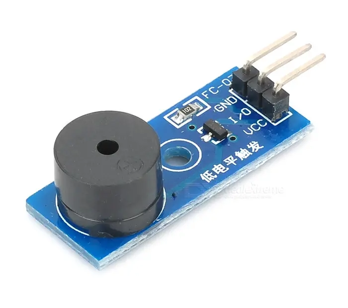
These modules generally have 3 pins i.e.
Vcc —-> around 3 to 5 V
Gnd —–> Ground
I/O —–> input to the buzzer inorder to control it’s sound
CubeMX Setup
In order to interface the buzzer, we have to provide a variable input to the buzzer and for that purpose, I will be using PWM to create a square wave of low frequency and also I will vary the duty cycle to observe the changes in the sound of the buzzer.
Open CubeMx and setup PWM channel output
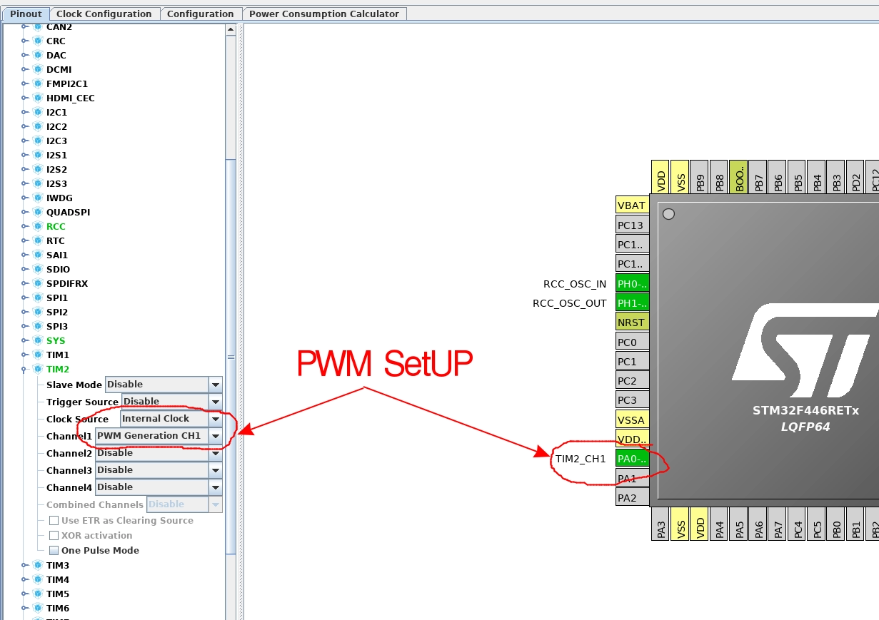
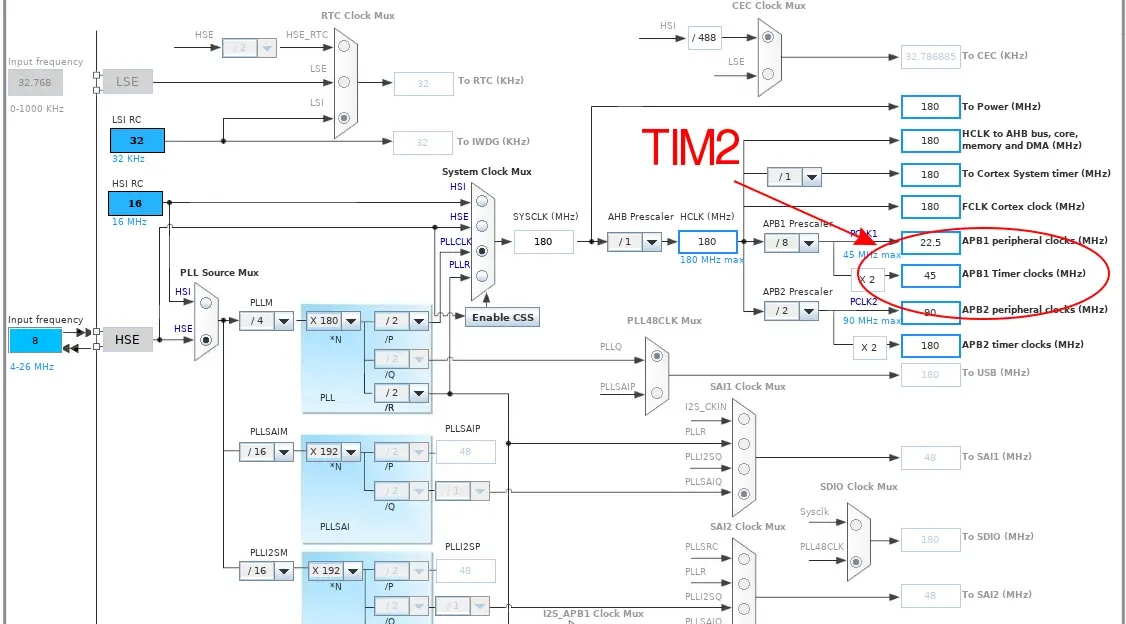
Next we need to set the clock. I am using TIM2, which is connected to the APB1 running at 45 MHz
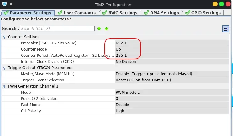
Now this part is important just like any other PWM application. We need to set the prescalar and ARR values. As the timer in my case is running at 45 MHz and also I want the duty cycle to vary between 0 to 255, the following is the calculation for the prescalar value
ARR = (45 MHz / (255*255)) = 692
ARR = 255
The reason for the values being ‘-1’ is because the minimum values here needs to be 0, which actually indicates at ‘1’ in the registers.
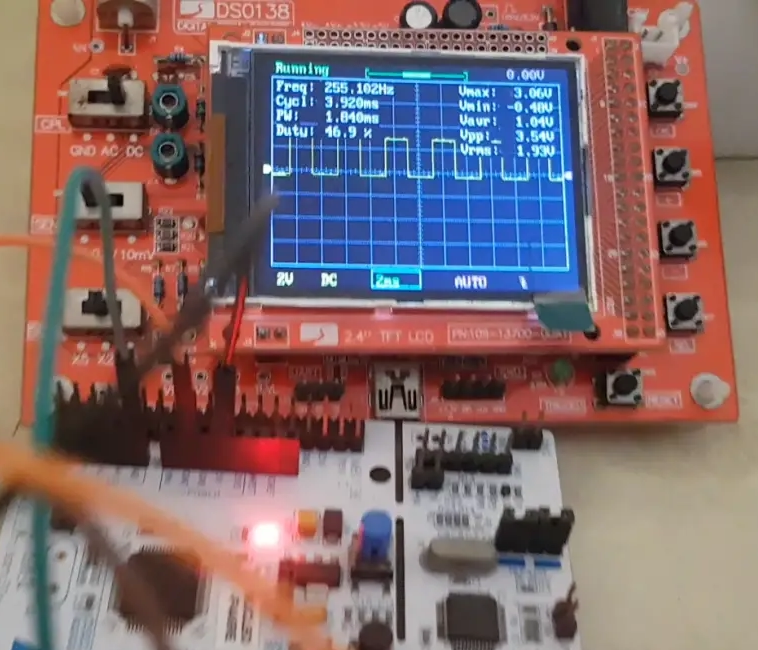
This setup will provide a frequency of (45000000/255*692) = 255 Hz and we can vary the duty cycle to observe the changes in the sound output.
Keep in mind that if the duty cycle is always 100% (i.e. 255), the output from the microcontroller will behave like digital high output and the buzzer won’t work.
Some Insight into the CODE
uint8_t value = 0; // the value for the duty cycle
while (value<255)
{
  htim2.Instance->CCR1 = value; // vary the duty cycle
  value += 20; // increase the duty cycle by 20
  HAL_Delay (500); // wait for 500 ms
}
value = 0; // reset the value
The duty cycle will increase every 500 ms and you can observe the changes in the sound of the buzzer. Watch the video in the last tab to see the changes.
Result


4 Comments. Leave new
Hi. great video. Yet one thing not clear: when you define TIM2_CH1 to GPIO port PA0, is this becoming Analog? is that the port you connect the buzzer to?
yes
Thank you. Constructive feedback: imagine somebody arriving to this page from a search engine… wouldn’t it be very useful to find a few words (or a link to them) explaining what HAL is, and what IDE is being used here?
Yeah sure. That’s a good advice. I will update few things and keep this in mind in my future tutorials.