

IR Remote with STM32
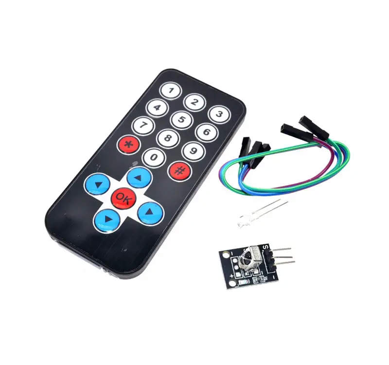
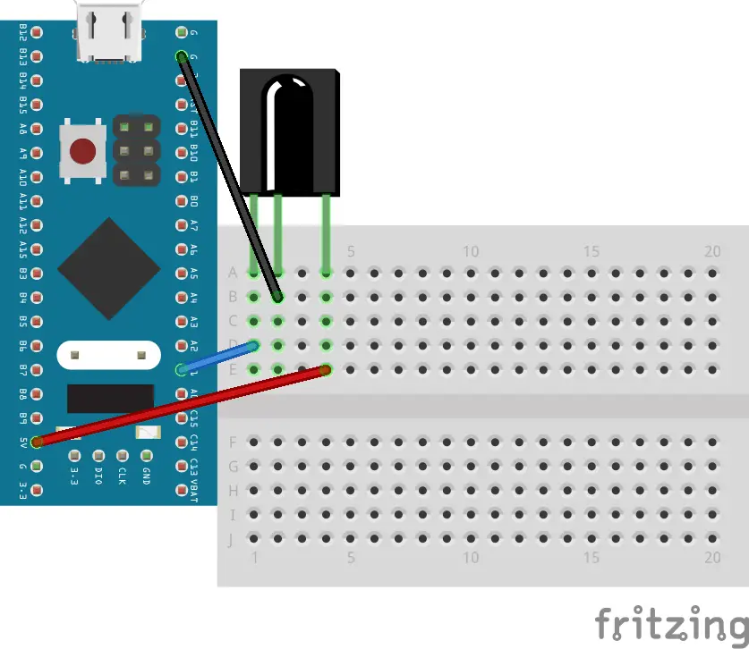
Today in this tutorial I am going to interface IR Remote with STM32 microcontroller. IR Remote Controllers and receivers follow some standard protocols for sending and receiving data. Some of these protocols are NEC , JVC , SIRC etc. Here we will be discussing only the NEC protocol. I will also use LCD16x2 to display the key pressed on the remote. But first let’s see what NEC protocol is.
What is NEC Protocol
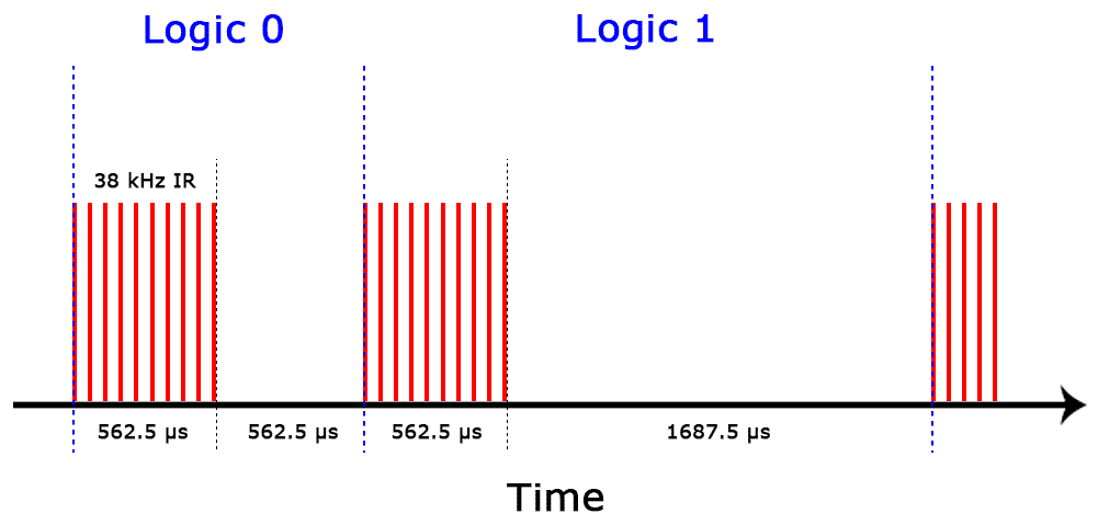
In NEC Protocol, a logic 0 is indicated by 562.5µs pulse burst followed by a 562.5µs space, with a total transmit time of 1.125ms and a logic 1 by 562.5µs pulse burst followed by a 1.6875ms space, with a total transmit time of 2.25ms.
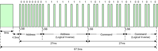
Whenever a key is pressed, the following is transmitted:-
1. A 9 ms leading pulse
2. A 4.5 ms space
3. The 8-bit address
4. The 8-bit logical inverse of the address
5. The 8-bit command
6. The 8-bit logical inverse of the command
7. Finally a 562.5µs pulse burst to show end of message transmission
How to Decode
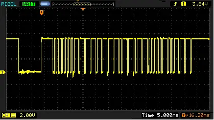
Decoding any IR protocol is not difficult at all. The IR receiver is a photodiode and pre-amplifier that converts the IR light into an electrical signal. It converts the active HIGH signal to active LOW. Also the signal pulse are continuous as shown in the picture below
Ok so in order to decode first we have to wait for the input pin to go low. Once the pin is LOW, we will wait for the pin to go HIGH. This should take around 9ms.
while (HAL_GPIO_ReadPin (GPIOA, GPIO_PIN_1));   // wait for the pin to go low
while (!(HAL_GPIO_ReadPin (GPIOA, GPIO_PIN_1)));  // wait for the pin to go high.. 9ms LOW
Again wait for the pin to go low, which should take around 4.5 ms. And this will conclude the Start of Frame.
while (HAL_GPIO_ReadPin (GPIOA, GPIO_PIN_1)); // wait for the pin to go lowNow we are going to read the 32 bits and store them in a variable. To read a bit, we are going to check the length of the SPACE followed by the 562.5µs. If this length is more than 1 ms, that means the bit is ‘1’. If the length is less than 1 ms the bit is ‘0’.
for (int i=0; i<32; i++)
{
  count=0;
  while (!(HAL_GPIO_ReadPin (GPIOA, GPIO_PIN_1))); // wait for pin to go high.. this is 562.5us LOW

  while ((HAL_GPIO_ReadPin (GPIOA, GPIO_PIN_1)))  // count the space length while the pin is high
 {
  count++;
  DWT_Delay_us(100);
 }

 if (count > 12) // if the space is more than 1.2 ms
 {
  data |= (1UL << (31-i));   // write 1
 }

 else data &= ~(1UL << (31-i));  // write 0
}
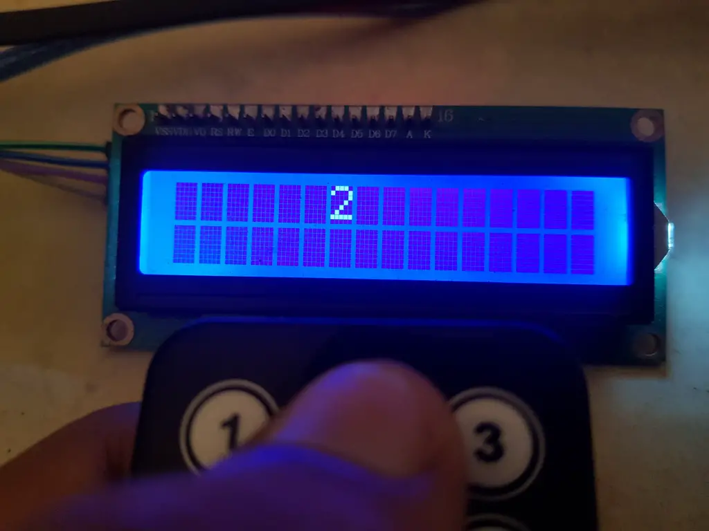
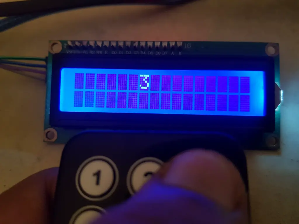
Next we need to assign the values to the key pressed on the Remote. I will also print these characters on the LCD. Below is the code to do that.
switch (code)
{
	case (0xFFA25D):
		lcd_send_cmd (0x86);
		lcd_send_data ('1');
		break;

	case (0xFF629D):
		lcd_send_cmd (0x86);
		lcd_send_data ('2');
		break;

	case (0xFFE21D):
		lcd_send_cmd (0x86);
		lcd_send_data ('3');
		break;

	case (0xFF22DD):
		lcd_send_cmd (0x86);
		lcd_send_data ('4');
		break;

	case (0xFF02FD):
		lcd_send_cmd (0x86);
		lcd_send_data ('5');
		break;

	case (0xFFC23D):
		lcd_send_cmd (0x86);
		lcd_send_data ('6');
		break;

	case (0xFFE01F):
		lcd_send_cmd (0x86);
		lcd_send_data ('7');
		break;

	case (0xFFA857):
		lcd_send_cmd (0x86);
		lcd_send_data ('8');
		break;

	case (0xFF906F):
		lcd_send_cmd (0x86);
		lcd_send_data ('9');
		break;

	case (0xFFB04F):
		lcd_send_cmd (0x86);
		lcd_send_data ('#');
		break;

	case (0XFF6897):
		lcd_send_cmd (0x86);
		lcd_send_data ('*');
		break;

	case (0xFF9867):
		lcd_send_cmd (0x86);
		lcd_send_data ('0');
		break;

	case (0xFF38C7):
		lcd_send_cmd (0x86);
		lcd_send_data ('K');
		break;

	case (0xFF18E7):
		lcd_send_cmd (0x86);
		lcd_send_data ('^');
		break;

	case (0xFF10EF):
		lcd_send_cmd (0x86);
		lcd_send_data ('<');
		break;

	case (0xFF5AA5):
		lcd_send_cmd (0x86);
		lcd_send_data ('>');
		break;

	case (0xFF4AB5):
		lcd_send_cmd (0x86);
		lcd_send_data ('u');
		break;

	default :
		break;
}
Result


11 Comments. Leave new
I am uploading the project on a BluePill board and on debugging, the “data” variable is not changing at all and the LCD is not receiving any data. Circuit verified as OK
Hey in the above delay,
it should be 1000 not 100 as it is 1ms and 1ms = 1000us
Please correct it
it is not intended for 1 ms. As we are checking for the delay of 1.2 ms, it’s not possible if we use 1 ms. That’s why that delay is for 0.1 ms
Cool, IR receiver is working! What about an IR transmitter? Have you tried to do this?
I haven’t done that. I don’t have any transmitter.
I did it. It is not a difficult as it seemed at first. I can share if you interested 😁
I am very interested about IR transmitter. Can u share ur project please. Thank u very much
I am interested too :p
Great idea, i was searching for something to decode RF signal, that has the same protocol of sending data, the only thing that is different is that on RF receiver is a lot of noise that i will need to filter out in the code. Thank you!
hi sir .im working in the same concept but in pic16f877a ir protocol interface and im getting random values .can you help me with this
that was so helpful would you please send me(email) the papers you have used for this?