

DS18B20 and STM32
I have covered few temperature sensors in the past eg- LM35, DHT11, DHT22 and also the internal temperature sensor of the STM32 itself. Today in this tutorial we will see how to interface DS18B20 temperature sensor with STM32.
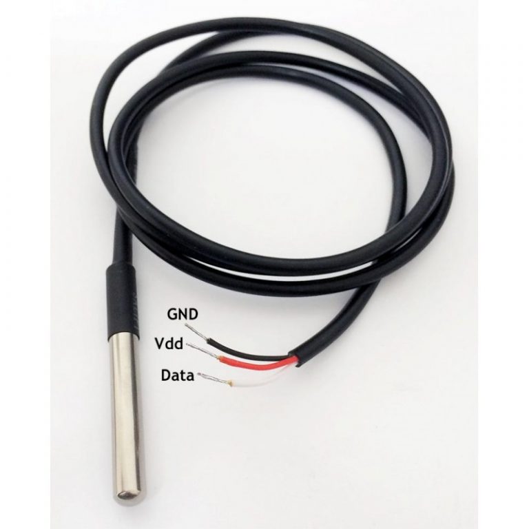
The DS18B20 digital thermometer provides 9-bit to 12-bit Celsius temperature measurements and has an alarm function with non-volatile user-programmable upper and lower trigger points. Like DHT11 and DHT22, DS18B20 also communicates over a 1-Wire bus that by definition requires only one data line for communication with the micro controller. Let’s see how to program a DS18B20 temperature sensor using STM32.
HOW TO
NOTE:- This code works with STM32CUBEIDE and it uses TIMER to create delay in microsecond. If you don’t know how to do that, go to https://controllerstech.com/create-1-microsecond-delay-stm32/ .
I am going to skip the Cube mx setup process as it’s usual one only. I am using pin PA1 as the data pin for the sensor and controller is running at it’s maximum frequency.
void delay (uint32_t us)
{
    __HAL_TIM_SET_COUNTER(&htim6,0);
    while ((__HAL_TIM_GET_COUNTER(&htim6))<us);
}
INITIALIZE

- In order for the sensor to work, we need to initialize it every time.
- According to the datasheet, the initialization is done by pulling the data pin LOW for 480 us and than reading the pin for the presence pulse sent by sensor. Here is the function for that
uint8_t DS18B20_Start (void)
{
	uint8_t Response = 0;
	Set_Pin_Output(DS18B20_PORT, DS18B20_PIN);   // set the pin as output
	HAL_GPIO_WritePin (DS18B20_PORT, DS18B20_PIN, 0);  // pull the pin low
	delay (480);   // delay according to datasheet

	Set_Pin_Input(DS18B20_PORT, DS18B20_PIN);    // set the pin as input
	delay (80);    // delay according to datasheet

	if (!(HAL_GPIO_ReadPin (DS18B20_PORT, DS18B20_PIN))) Response = 1;    // if the pin is low i.e the presence pulse is detected
	else Response = -1;

	delay (400); // 480 us delay totally.

	return Response;
}
WRITE

- To write a BIT to the sensor, we need to perform some operation on the data line.
- To generate a Write 1, after pulling the line low, the master must release the line within 15µs.
- When the bus is released, the 5kΩ pullup resistor will pull the bus high.

- To generate a Write 0 time slot, after pulling the line low, the master must continue to hold the line low for the duration of the time slot (at least 60µs).
void DS18B20_Write (uint8_t data)
{
	Set_Pin_Output(DS18B20_PORT, DS18B20_PIN);  // set as output

	for (int i=0; i<8; i++)
	{

		if ((data & (1<<i))!=0)  // if the bit is high
		{
			// write 1

			Set_Pin_Output(DS18B20_PORT, DS18B20_PIN);  // set as output
			HAL_GPIO_WritePin (DS18B20_PORT, DS18B20_PIN, 0);  // pull the pin LOW
			delay (1);  // wait for 1 us

			Set_Pin_Input(DS18B20_PORT, DS18B20_PIN);  // set as input
			delay (50);  // wait for 60 us
		}

		else  // if the bit is low
		{
			// write 0

			Set_Pin_Output(DS18B20_PORT, DS18B20_PIN);
			HAL_GPIO_WritePin (DS18B20_PORT, DS18B20_PIN, 0);  // pull the pin LOW
			delay (50);  // wait for 60 us

			Set_Pin_Input(DS18B20_PORT, DS18B20_PIN);
		}
	}
}
READ
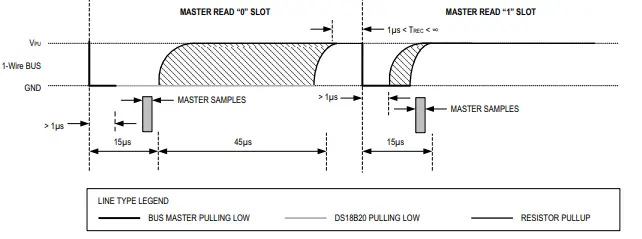
- A read time slot is initiated by the master device pulling the 1-Wire bus low for a minimum of 1µs and then releasing the bus.
- After the master initiates the read time slot, the DS18B20 will begin transmitting a 1 or 0 on bus.
- It transmits a 1 by leaving the bus high and transmits a 0 by pulling the bus low.
- When transmitting a 0, the sensor will release the bus by the end of the time slot, and the bus will be pulled back to its high idle state by the pull-up resister.
uint8_t read (void)
{
	uint8_t value=0;
	gpio_set_input ();

	for (int i=0;i<8;i++)
	{
		gpio_set_output ();   // set as output

		HAL_GPIO_WritePin (GPIOA, GPIO_PIN_1, 0);  // pull the data pin LOW
		delay (2);  // wait for 2 us

		gpio_set_input ();  // set as input
		if (HAL_GPIO_ReadPin (GPIOA, GPIO_PIN_1))  // if the pin is HIGH
		{
			value |= 1<<i;  // read = 1
		}
		delay (60);  // wait for 60 us
	}
	return value;
}
Main Function
The following are the STEPS, we need to follow to read the temperature from DS18B20
Presence = DS18B20_Start ();
HAL_Delay (1);
DS18B20_Write (0xCC);  // skip ROM
DS18B20_Write (0x44);  // convert t
HAL_Delay (800);

Presence = DS18B20_Start ();
HAL_Delay(1);
DS18B20_Write (0xCC);  // skip ROM
DS18B20_Write (0xBE);  // Read Scratch-pad

Temp_byte1 = DS18B20_Read();
Temp_byte2 = DS18B20_Read();
Result


33 Comments. Leave new
Hi!
I have a project and using several Task in RTOS.
One of the task is DS18B20 Driver Code that use above Code.
When DS18B20 not connect to stm32, the another task dont run.
Can you help me?
Maybe the blocking mode is an issue. Try using this one https://controllerstech.com/multiple-ds18b20-sensors-using-uart/
why i have error:
conflicting types for ‘DS18B20_Start’
check if you are using some other library also… There is no way there can be a conflicting types, as it is only defined once.
Где узнать про ds18b20 stm32
Thank you a lot for your effort 🙂 I have a problem. I am using STM32L031K6T6. Your function “SetInput” and “Set Output” took me 40us each. so there is no possibility to wait only 1 us. Can you please give me an advice? thanks
hi, thanks for the code. But it cant read negative temperature values so how I need to modify the code to also do that.
Hello
I tried to connect DS2431 eeprom according to your explanations. It looks like very similar . But i could not read or write it. we will be grateful if you use DS2431 eeprom in your next videos . Thanks for your supports .
Can you do same video with more sensor ds18b20, for example 4 or 5 (like example 1 in datasheet )?
Hi,
Thanks for you code… I used to get a faster result.
But I needed to correct few things…
This is my version which could help someone surfing here ^^
Context : NRF52 (ARM cortex M3) and some custom functions for delays… I’m pretty confident it can work on STM32, with few changes in the macos.
————-
/*
* DS18B20.c
*
* Created on: 3 mai 2021
* Author: Nirgal
*/
#include “../appli/config.h”
#if USE_DS18B20
#include “../appli/common/systick.h”
#include “../appli/common/gpio.h”
#ifndef DS18B20_PIN
#define DS18B20_PIN (13)
#endif
#define DS18B20_delay_us SYSTICK_delay_us
#define DS18B20_delay_ms SYSTICK_delay_ms
#define DS18B20_pin_write(x) GPIO_write(DS18B20_PIN, x);
#define DS18B20_pin_read() GPIO_read(DS18B20_PIN)
static volatile bool_e initialized = FALSE;
static uint8_t DS18B20_Start (void);
static void DS18B20_Write (uint8_t data);
static uint8_t DS18B20_Read (void);
void DS18B20_init(void)
{
if(!initialized)
{
GPIO_configure_input_output_opendrain(DS18B20_PIN, GPIO_PIN_CNF_PULL_Pullup); // set the pin as output opendrain
initialized = TRUE;
}
}
int16_t DS18B20_get_temperature(void)
{
uint8_t msb, lsb;
msb = 0;
lsb = 0;
uint8_t presence;
if(!initialized)
DS18B20_init();
presence = DS18B20_Start();
if(presence)
{
SYSTICK_delay_us(1000);
DS18B20_Write (0xCC); // skip ROM
DS18B20_Write (0x44); // convert t
DS18B20_delay_ms(800);
presence = DS18B20_Start();
if(presence)
{
DS18B20_delay_us(1000);
DS18B20_Write (0xCC); // skip ROM
DS18B20_Write (0xBE); // Read Scratch-pad
msb = DS18B20_Read();
lsb = DS18B20_Read();
}
}
return U16FROMU8(msb, lsb);
}
static uint8_t DS18B20_Start (void)
{
uint8_t response = 0;
DS18B20_pin_write(0); // pull the pin low
DS18B20_delay_us(480); // delay according to datasheet
DS18B20_pin_write(1);
DS18B20_delay_us(80); // delay according to datasheet
if (!(GPIO_read(DS18B20_PIN)))
response = 1; // if the pin is low i.e the presence pulse is detected
DS18B20_delay_us(400); // 480 us delay totally.
return response;
}
static void DS18B20_Write (uint8_t data)
{
for(int i=0; i<8; i++)
{
if((data & (1<<i))!=0) // if the bit is high
{ // write 1
DS18B20_pin_write(0); // pull the pin LOW
DS18B20_delay_us(1); // wait for 1 us
DS18B20_pin_write(1);
DS18B20_delay_us(60); // wait for 60 us
}
else // if the bit is low
{ // write 0
DS18B20_pin_write(0);
DS18B20_delay_us(60); // wait for 60 us
DS18B20_pin_write(1);
DS18B20_delay_us(15); //wait for pull up !
}
}
}
static uint8_t DS18B20_Read (void)
{
uint8_t value=0;
for(int i=0;i<8;i++)
{
DS18B20_pin_write(0); // pull the data pin LOW
DS18B20_delay_us(2); // wait for 2 us
DS18B20_pin_write(1); // set as input
DS18B20_delay_us(10); // wait for pullup if the sensor do not write 0
if(DS18B20_pin_read()) // if the pin is HIGH
{
value |= 1<<i; // read = 1
}
DS18B20_delay_us(50); // wait for the remaining 50 us (50+10 = 60)
}
return value;
}
#endif
Sorry about inverting lsb & msb in this code…
You should read in this order:
lsb = DS18B20_Read();
msb = DS18B20_Read();
and if you want display the result:
int16_t temperature = DS18B20_get_temperature();
printf(“%d.%04d°C\n”,temperature/16, 625*(temperature%16));
hi nirgal, thanks for your code, and can you give me the code of functions DS18b20_delay_us(50)?? many thanks
Gracias amigo, saludos desde mi amada Venezuela.
Thanks friend, greetings from my beloved Venezuela.
öncelikle merhaba indirdiğim kodu açamıyorum yardımcı olur musunuz.
why temper=tem/16
because the sensitivity is .0625 per bit. please check the datasheet
Please, seeng this example, I tried implement for multiple sensors but I can’t to do this, anybody can help me
Hi, I used the code as instructed, no errors no warnings, i m using stm32f407 discovery board. But no response, the temperature isn’t appearing (in the debug mode, i didn’t use LCD). I enabled tim1 ( APB2= 100 MHZ, prescaler= 100-1, and period= 0xffff-1). And in the main I used the function ( HAL_TIM_BASE_START(&htim).
It should work alright. Debug the code, and check where the execution is stuck.
i update the delay function too:
void Delay (uint_16 us)
{
HAL_TIM_BASE_Start(&htim1);
__HAL_TIM_SET_COUNTER(&htim1,0);
while ((__HAL_TIM_GET_COUNTER(&htim1))<us);
HAL_TIM_BASE_Stop(&htim1);
}
and the counter period to 1.
t=(100-1/100000000)*1.
the same no response.
there is no debug execution stuck . i put many break points, and the code run well and stops at the break points. but no temperature value.
Have you connected the pull up resistor to the data pin ?
I would like to see the code.
Mail me admin@controllerstech.com
Or telegram @controllerstech
I really appreciate what you are doing ..when I’m watching youtube tutorial and hear background music which is exclusive for your tutorial ..it makes me cheerfull ..because I am sure that it is going to work out..thanks for that, keep it on I learn a lot from you.
Hi, thx for good projekt. Can you say me , how does work read function by Value? I have Problem with value |= 1<<i.
Value must be OR with (1<< i) and i must schift 1 bit to Right ?
THX
We are reading the pin and if the pin is HIGH, we are shifting ‘1’ to that place.
I would like to know how do I use more than one sensor on the same pin with these functions?
I will work on it soon.
hello admin !
did you something about more than one sensor ?
thanks
very good the text. I would like to know how to read more than one sensor on the same pin? That is possible with this code ?
up
Hi!! I like very very much your tutorials, thank you very much!!
It would be nice to have the correct source files for the ds18b20, as they are for i2c lcd. Could you, please, provide the files accordingly?
Many thanks and best regards!!
Luiz
sure will do that in future tutorial
Hi!
This description very good, need attention read all material.
Simple code and algorithm usability peripheries, me like this site 🙂
Good Luck!