

How to use SPI with STM32
I have written many posts about interfacing I2C devices with STM32 but there are some devices which require only SPI to work i.e. SD card reader, TFT display etc. So today in this post, we are going to learn how to use SPI with STM32.
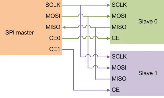
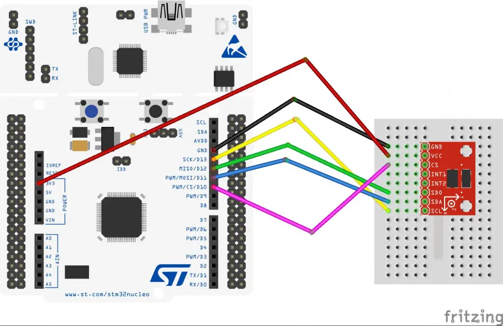
SPI (Serial Peripheral Interface) generally requires 4 wires as shown above. The names are as follows:-
SCK –> Serial Clock
MOSI –> Master out Slave In is used to send data to slave
MISO –> Master In Slave Out is used to receive data from slave
CE/CS –> Chip Select is used for selecting the slave
SPI is not very different from I2C. It just require more wires and the process of selecting the slave is a little different. In order to enable a slave device, we need to pull the CS pin low and after our read or write is complete, just pull the pin high again. This will disable the slave device.
HOW TO
I am going to show you working with an actual hardware and because of lack of many SPI devices, I will work with whatever I have and that is ADXL345. I have already wrote a tutorial about How to use this device with I2C. Do check it out because I am not going to explain the register part but only focus on How to read and write data using SPI.
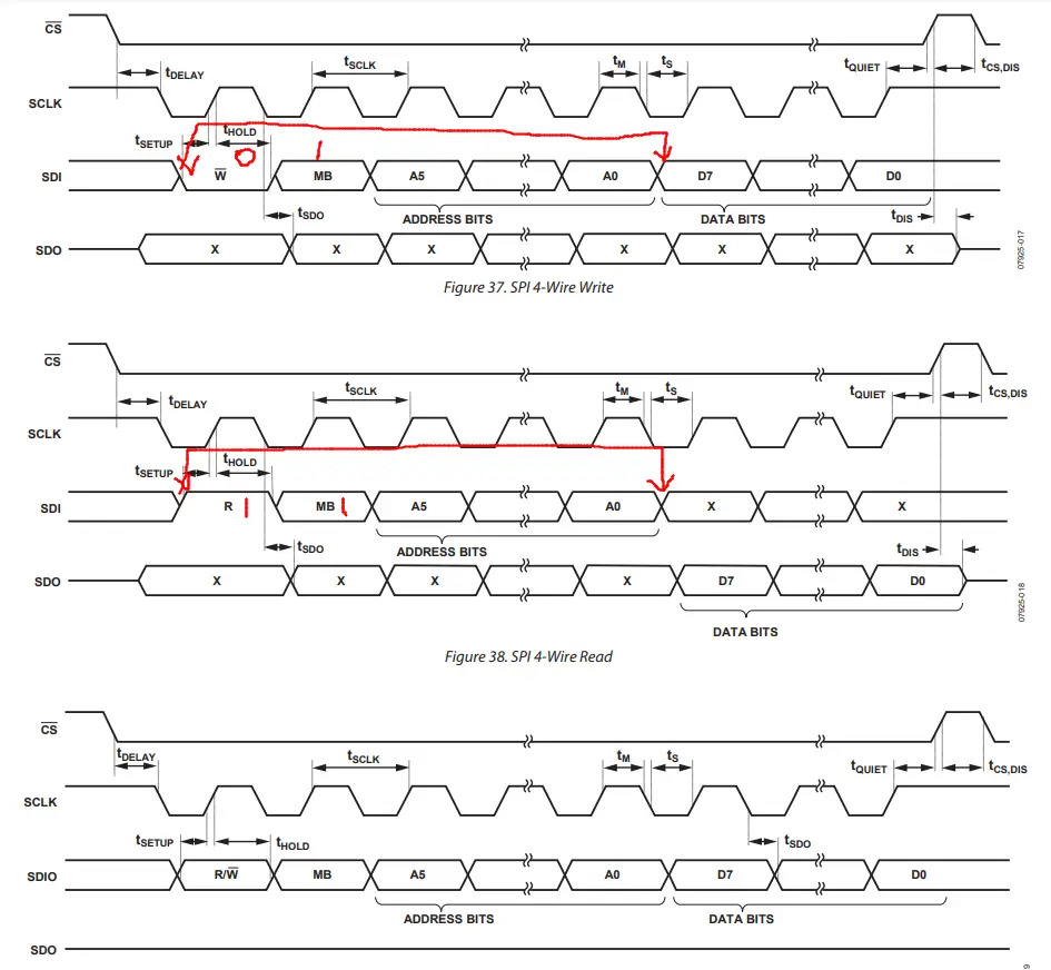
So before start setting up the CubeMx, Let’s check the datasheet of ADXL345 to understand the requirements for the SPI.
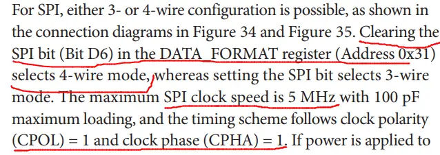
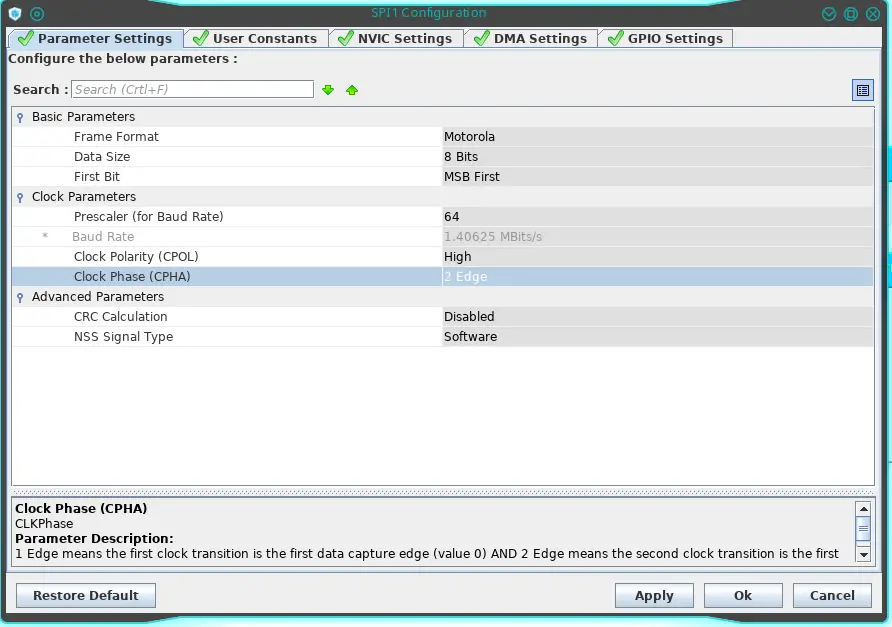
According to the figure above, We need to setup SPI with clock speed less than 5MHz and also CPOL =1 and CPHA =1. I will be using the 4 wire mode so let’s set it up.. Below is the screenshot of the SPI setup window
Some Insight into the CODE
ADXL WRITE FUNCTION
void adxl_write (uint8_t address, uint8_t value)
{
	uint8_t data[2];
	data[0] = address|0x40;  // multibyte write
	data[1] = value;
	HAL_GPIO_WritePin (GPIOB, GPIO_PIN_6, GPIO_PIN_RESET);  // pull the cs pin low
	HAL_SPI_Transmit (&hspi1, data, 2, 100);  // write data to register
	HAL_GPIO_WritePin (GPIOB, GPIO_PIN_6, GPIO_PIN_SET);  // pull the cs pin high
}- pull the CS low to enable the slave
- transmit the address to which we want to write data
- transmit the data
- pull the CS pin high to disable the slave
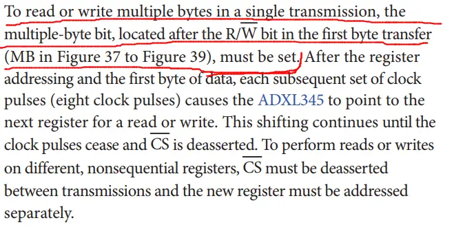
NOTE that in data[0], address is OR with 0x40. This is for multibyte writing. It informs ADXL that we want to transfer more than one byte in a single transmission. According to ADXL datasheet, this byte should be high if you want to do that.
ADXL READ FUNCTION
void adxl_read (uint8_t address)
{
	address |= 0x80;  // read operation
	address |= 0x40;  // multibyte read
	uint8_t rec;
	HAL_GPIO_WritePin (GPIOB, GPIO_PIN_6, GPIO_PIN_RESET);  // pull the pin low
	HAL_SPI_Transmit (&hspi1, &address, 1, 100);  // send address
	HAL_SPI_Receive (&hspi1, data_rec, 6, 100);  // receive 6 bytes data
	HAL_GPIO_WritePin (GPIOB, GPIO_PIN_6, GPIO_PIN_SET);  // pull the pin high
}
Here we are reading using the following steps:-
- pull the CS low to enable the slave
- transmit the address from where we want to read data
- receive data. 6 bytes in this case
- pull the CS pin high to disable the slave
NOTE that address is OR with 0x80 and 0x40. That’s because according to ADXL datasheet, If we want to read data, we need to set the last bit HIGH and also for multibyte read/write the 6th bit must be HIGH
ADXL INITIALIZATION FUNCTION
void adxl_init (void)
{
	adxl_write (0x31, 0x01);  // data_format range= +- 4g
	adxl_write (0x2d, 0x00);  // reset all bits
	adxl_write (0x2d, 0x08);  // power_cntl measure and wake up 8hz
}
This is explained in my previous tutorial in detail. Anyway comments are self explanatory.
Result


6 Comments. Leave new
hi, i try the above step to implement spi1 in stm32f3 register all are same but i am not 100% during the transmission and reception i am getting some garbage data in the receiver buffer when check the spi->dr i found it showing 0xffff please suggest me what could i have done wrong so that spi1 work correctly.
can you use SPI in PL1167?
YOU can use the AD7705 , it also use the SPI to communication to the MCU , but if you use AD7705 ,you must modification the parameter
Hello, I have tried your same code for ADXL375 using a STM32F401 and truestudio. I have put the right values for the cpol and the cpha and my speed is less than 5MHz. However, when i try getting the device ID i get rubbish (the value changes each time i run the program) and when i read the different axes I get really strange values especially for the z axis. Basically, nothing is working. While debugging it seems that only MOSI line is working (MISO no). I have measured with oscilloscope as well but got no clear information. I really dont know what else to do. if you know what it could be it would help a lot.
Don’t use SPI. First Try using I2C I have written a tutorial using I2C. You can search that wihtin the website itself.
I am using SPI because I am programming various ADXL375, so I would like to be able to at least gather measurements from one